ARC HS Development Kit
The ARC HS Development Kit (HSDK) Platform supports the ARC HS34, HS36 and HS38x4 quad core processors running at 1GHz. The ARC HSDK features 256 kByte of on-chip SRAM and 4 GByte of DDR3-SDRAM. The software available from Synopsys for the ARC HSDK includes pre-built SMP Linux image (plus the U-boot bootloader) and the embARC OSP distribution for embedded systems. embARC OSP source code includes bare metal and FreeRTOS device drivers and example applications. Code development is made easy using the MetaWare Development Toolkit, MetaWare Lite tools or the ARC GNU Tool Chain.
See also this URL for details about the board: DesignWare ARC HS Development Kit (HSDK)
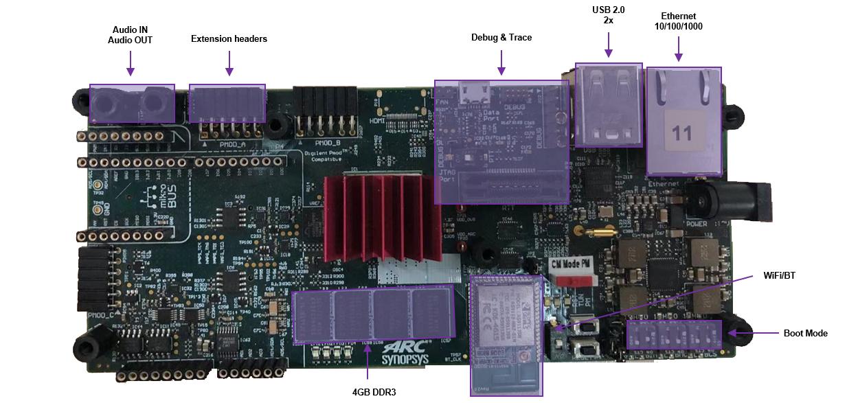
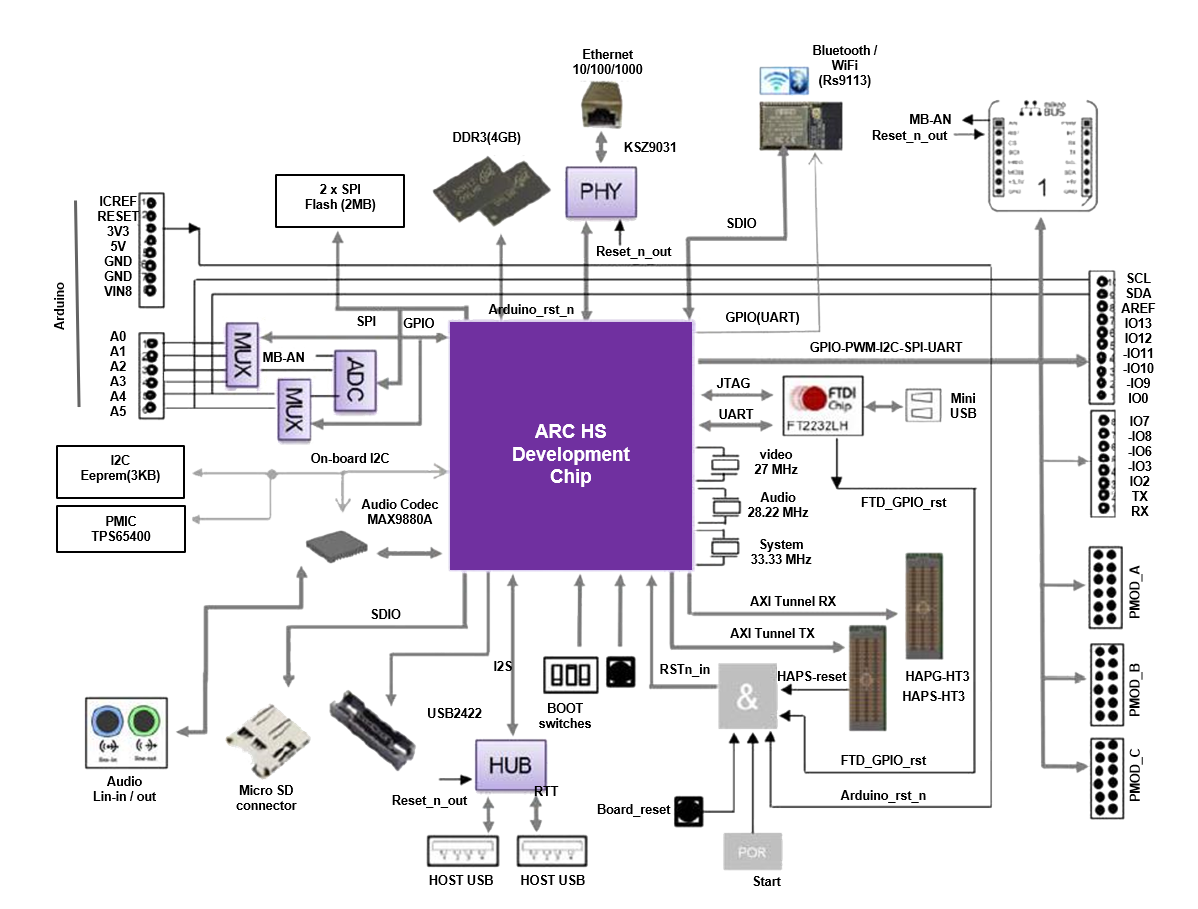
The ARC HS Development Kit features the following components:
ARC HS SoC:
Quad Core HS38x4 Processor
DDR3 memory controller
GPU
USB, Ethernet, SDIO
DesignWare APB Peripherals (consult HSDK documentation for complete details)
- Memory / Storage:
DDR3-1333 (4 GB)
2x SPI Flash (2 MB)
I2C EEPROM (3 KB)
- Interfaces:
USB2 (2x)
Ethernet (10/100/1000)
Audio - line in/out
USB Data port (JTAG/UART)
Micro-SD Card
WIFI/BT module
ADC (6 channels)
RTT Nexus and JTAG connectors
- Extensions:
AXI Tunnel (32-bit, 150 MHz)
Arduino - Interface headers (UNO R3 compatible)
mikroBUS headers
PMOD Interfaces (3x), PMOD A and PMOD B (12 pins), PMOD C (6 pins)
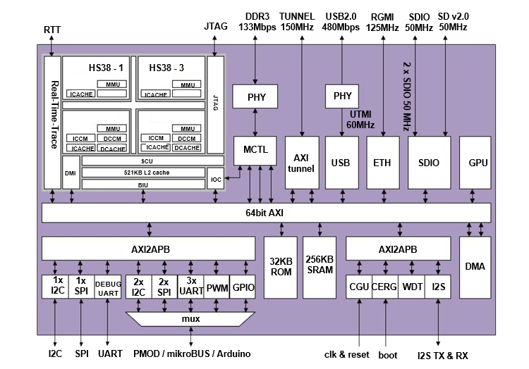
The ARC HS SoC provides the following main features:
Flexible, customizable IC architecture
Configurable / programmable boot scenarios
Configurable / programmable memory map
DesignWare HS38x4 quad-core @ 1GHz
64kByte instruction cache
64kByte data cache
256kByte ICCM (2 cores)
256kByte DCCM (2 cores)
Memory Management Unit
Physical Address Extension (PAE)
512kByte system level cache
Support for IO coherency
Support for Real-Time Trace
Vivante GC7000 NanoUltra3T GPU Processing Unit @ 400Mhz
Flexible clock generation
system clocks
33MHz system reference clock input
PLL for DDR clock
PLL for TUNNEL clock
PLL for ARC clock
PLL for all other system clocks
audio
audio reference clock input (24.576 MHz)
integer divider(s) for audio serial clock
256kByte SRAM
DDR3 interface
max speed grade DDR-1600 (800MHz)
data width 32 bits
max row address width 16 bits
max bank address width 3 bits
max 2 memory ranks
max supported DDR memory size is 4GByte
I2S TX / RX interface
USB 2.0 Host interface
SDIO interfaces
10/100/1000Mbps Ethernet RGMII interface
AXI tunnel interface
source-synchronous
max freq 150MHz
max data throughput 600MByte/s
UART interfaces
I2C interfaces
SPI interfaces
PWM interfaces
JTAG interface
Extension Interfaces
To bring your application context around the ARC HSDK, the following peripheral module standards are supported:
Digilent PMOD™ (3x)
MikroBUS (1x)
Arduino (1x)
For the details of extension interfaces, please go for the user manual/datasheet of HSDK. Users can change the interface configuration through the pinmux API in dev_pinmux.h.
Note
In the examples of embARC OSP, PMOD_B is used to connected SPI devices with PMOD interface, e.g. PMOD WiFI, PMOD_A is used to connected I2C devices with PMOD interface, e.g. PMOD ADC.
Programming and Debugging
Required Hardware and Software
To use embARC OSP applications on the IoTDK board, the following items are required
USB Cable
The universal switching power adaptor (110-240V AC to 12V DC), can be used to power the board
(optional) A collection of PMODs and Arduino modules.
Set up the HSDK
The HSDK boot switches are shown below. There are multiple configurations, such as boot mirror, boot image location, boot start mode, core selection and multi-core mode. For example, the configurations in the following picture are boot image location: 0x1 (internal ROM), boot start mode: generate cpu_start autonomously after reset, core selection: 0x0 (HS38X4_0), and multi-core mode: 0x0 (signal-core). For complete HSDK information, see the HS Development Kit User’s Guide provided with the HSDK.
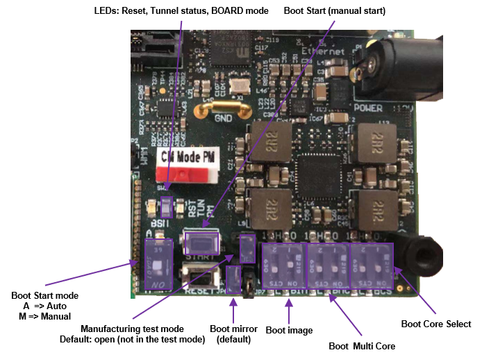
ARC HSDK DIP switch settings
Connect the USB cable to the HSDK mini-USB connector and to the USB port on your development host. If using the Ashling Opella-XD for ARC Debug Probe or Digilent JTAG-HS2 Probe, connect it to the right connector. Connect the power supply to the board and to the power outlet.
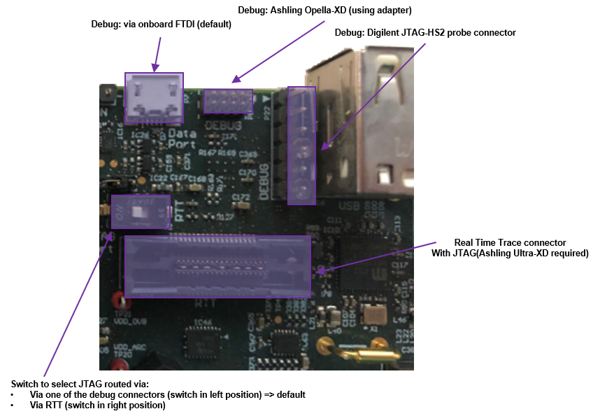
ARC HSDK debug interface
You can use any terminal emulation program to view UART output from the HSDK. The USB connection provides both the debug channel and RS232 transport. Use Tera Term in Windows as an example.
Determine which COM port the HSDK is using.
Open the Windows Control Panel and select Device Manager in a Windows environment.
Expand Ports (COM and LPT) in the list. Select USB Serial Port (COM x) and Note the COM port number for the ARC board.
Configure serial terminal connection.
Launch Tera Term. Select Serial in Setup. Choose the appropriate COM port string in Port and 115200 in Baud rate, 8 bits data, 1 stop bit, no parity (115200-8-N-1). Click OK to set the port configuration.
You can optionally save your settings so they can be easily retrieved.
Select New connection in File and choose the appropriate COM in Serial.
Test serial output with HSDK.
Press the “RESET” button on the HSDK board to reset the board.
Confirm that you can see the header and self-test message printed to the console.
********************************
**       Synopsys, Inc.       **
**   ARC HS Development Kit   **
********************************
** IC revision: Rev 1.0
Bootloader revision: Jun 12 2016, 08:54:06
Bootloader location: 0x1 (internal ROM)
Bootloader aux: 0x9 (sg15E,4Gb,x8,2r)
Bootloader speedmode: Slow
Bootloader multicore: 0x0 (Single-core)
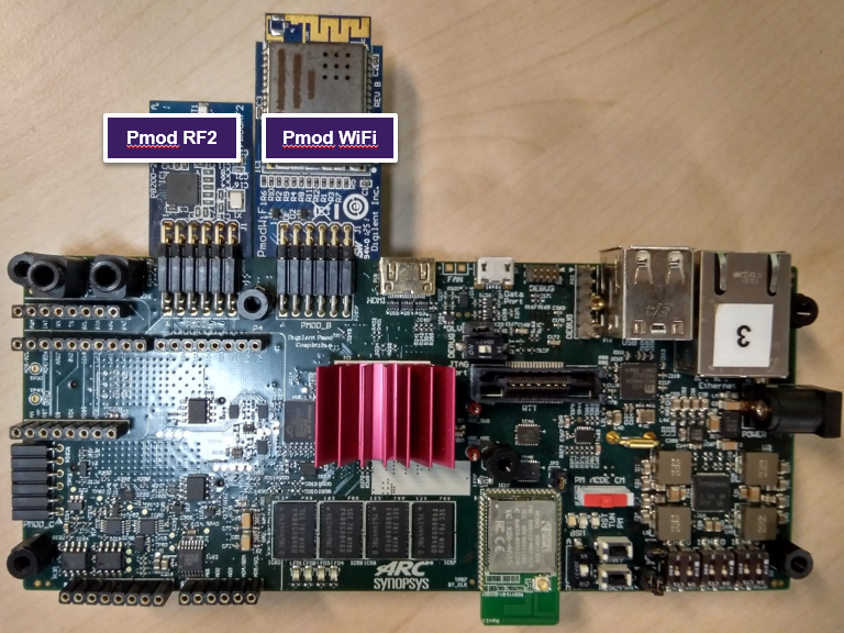
(Optional) Connect the PmodWiFi and PmodRF2 to the HSDK as shown.
Building
Take example_blinky as an example
cd embarc_osp\example\baremetal\blinky
# for ARC GNU toolchain
make TOOLCHAIN=gnu BOARD=hsdk
# for MWDT toolchain
make TOOLCHAIN=mw BOARD=hsdk
Running
cd embarc_osp\example\baremetal\blinky
# for ARC GNU toolchain
make TOOLCHAIN=gnu BOARD=hsdk run
# for MWDT toolchain
make TOOLCHAIN=mw BOARD=hsdk run
Debugging
cd embarc_osp\example\baremetal\blinky
# for ARC GNU toolchain
make TOOLCHAIN=gnu BOARD=hsdk gui
# for MWDT toolchain
make TOOLCHAIN=mw BOARD=hsdk gui
Flashing
The related introduction is working in progress.