ARC EM Starter Kit
Introduction
The DesignWare® ARC® EM Starter Kit (EMSK, emsk) enables rapid software development, code porting, software debugging, and profiling for ARC EM4, EM6 (EMSK 1.1), EM5D, EM7D, EM9D and EM11D (EMSK 2.3) processors.
Note
Caches are not integrated in EM5D and EM9D configurations. If program code runs in DDR memory, SPI and IIC devices should run at a slower frequency. EMSK 1.0 must be upgraded to EMSK 1.1 using EMSK 1.1’s firmware, EMSK 2.0, 2.1 and 2.2 must be upgraded to EMSK 2.3 using EMSK 2.3’s firmware.
The EMSK consists of a hardware platform and a software package, including pre-installed FPGA images of different configurations of the ARC EM Processor with peripherals.
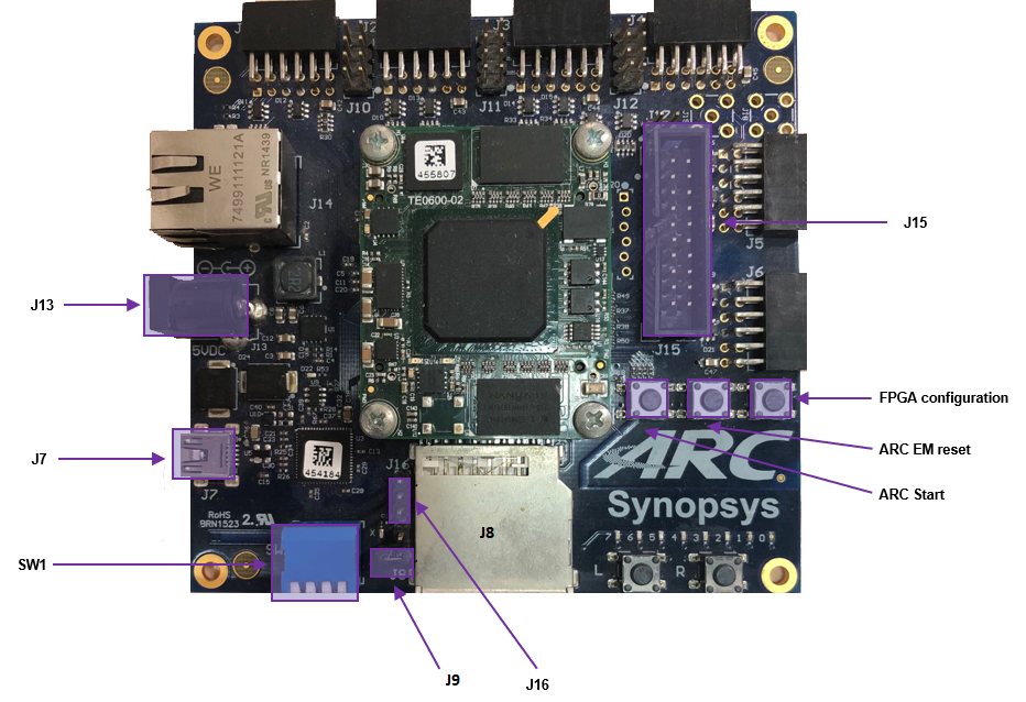
The development board is based on a Xilinx Spartan-6 LX45 FPGA. It supports hardware extensions using six 2x6 connectors supporting a total of 48 user I/O pins (plus power and ground pins) that can be used to connect components such as sensors, actuators, memories, displays, buttons, switches, and communication devices. A Digilent Pmod™ compatible extension board containing a four-channel 12-bit A/D converter with an IIC interface and an AC power adapter are included in the package.
Usage
EM core configurations
The FPGA board includes a SPI flash storage device pre-programmed with FPGA images containing different configurations of DesignWare® ARC EM cores.
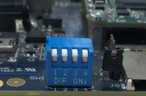
The FPGA image can be selected using the pins 1 and 2 of the SW1 switch on the board:
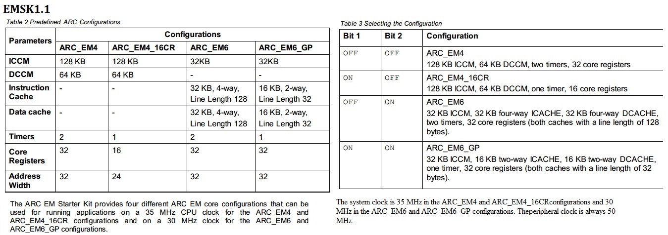
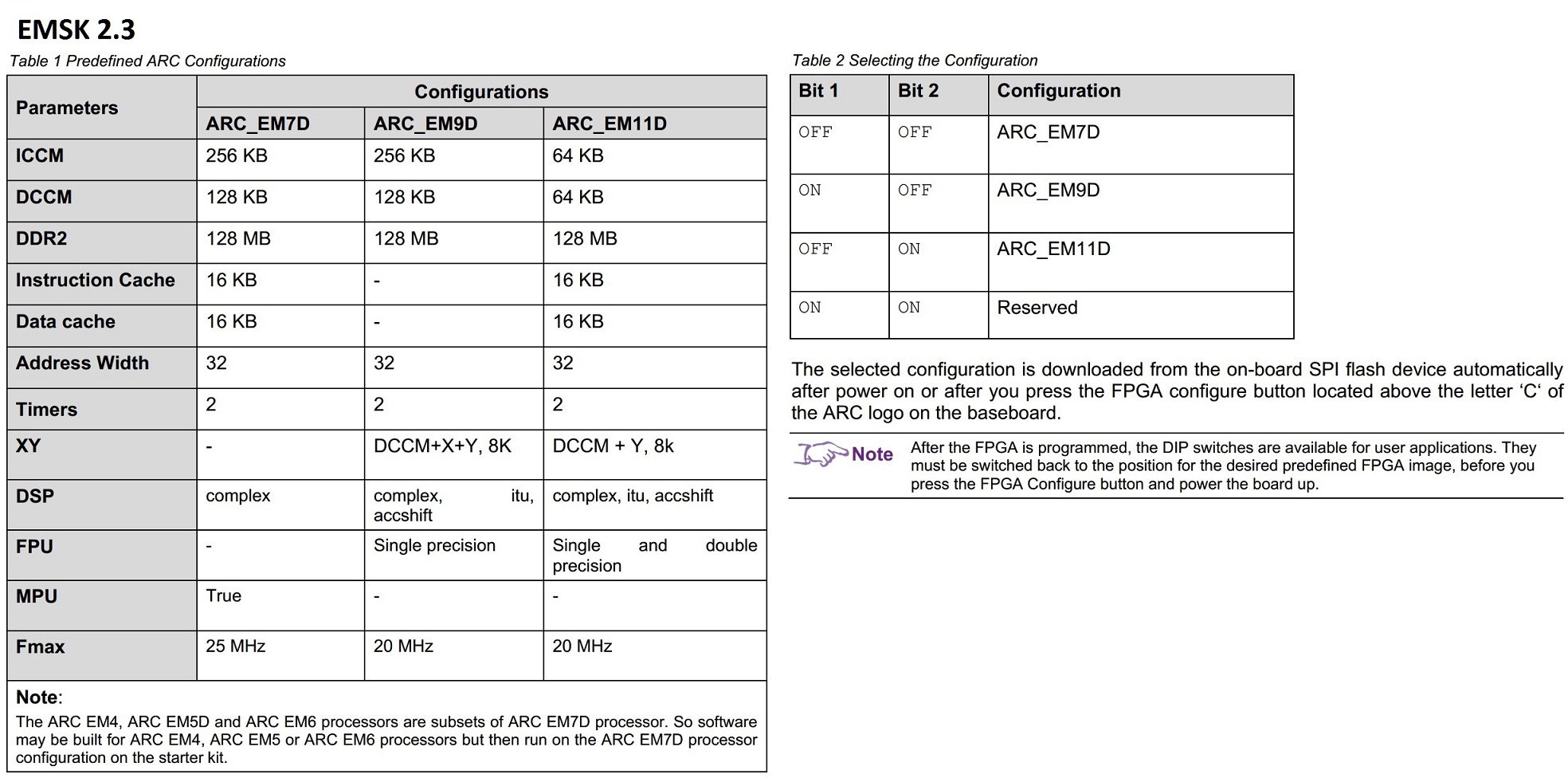
The following tables provide the details of supported EM Core configurations for different suported versions of EMSK board.
Peripherals
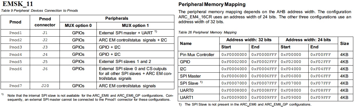
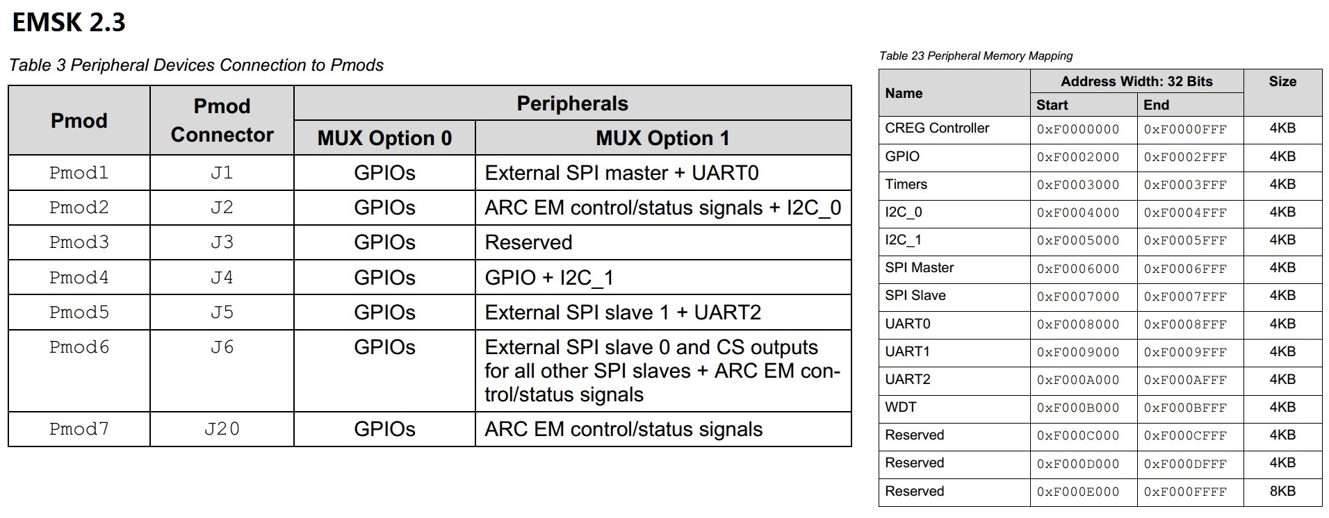
There are many peripheral devices available, such as SPI master, SPI slave, IIC, UART, GPIO. External hardware interface devices can be connected to the EMSK using Pmod Connectors. The Pmod connectors are controlled by Pmod mux controller.
The peripheral memory mapping depends on the AHB address width. The configuration ARC_EM4_16CR uses an address width of 24 bits. The other configurations use an address width of 32 bits. The peripheral connections and memory mappings for different supported versions of EMSK board are shown below:
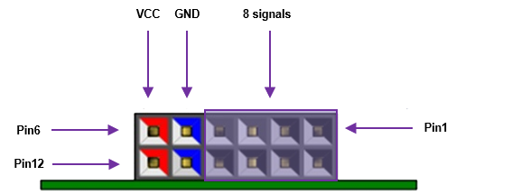
PMOD pins Definition
The location of the pins on the PMOD connectors is shown:
POMD1(J1) |
POMD2(J2) |
||||
|---|---|---|---|---|---|
Pins |
CFG1 |
CFG2 |
Pin |
CFG1 |
CFG2 |
1 |
Port C[8] |
UART1_CTS |
1 |
Port C[12] |
run_req |
2 |
Port C[9] |
UART1_TXD |
2 |
Port C[13] |
run_ack |
3 |
Port C[10] |
UART1_RXD |
3 |
Port C[14] |
I2C0_SCL |
4 |
Port C[11] |
UART1_RTS |
4 |
Port C[15] |
I2C0_SDA |
5 |
GND |
GND |
5 |
GND |
GND |
6 |
3V3 |
3V3 |
6 |
3V3 |
3V3 |
7 |
Port A[8] |
SPI1_CS_N |
7 |
Port A[12] |
halt_req |
8 |
Port A[9] |
SPI1_MOSI |
8 |
Port A[13] |
halt_ack |
9 |
Port A[10] |
SPI1_MISO |
9 |
Port A[14] |
N.C |
10 |
Port A[11] |
SPI1_SCLK |
10 |
Port A[15] |
N.C |
11 |
GND |
GND |
11 |
GND |
GND |
12 |
3V3 |
3V3 |
12 |
3V3 |
3V3 |
POMD3(J3) |
POMD4(J4) |
||||
|---|---|---|---|---|---|
Pins |
CFG1 |
CFG2 |
Pin |
CFG1 |
CFG2 |
1 |
Port C[16] |
N.C |
1 |
Port C[20] |
Port D[4] |
2 |
Port C[17] |
N.C |
2 |
Port C[21] |
Port D[5] |
3 |
Port C[18] |
N.C |
3 |
Port C[22] |
I2C1_SCL |
4 |
Port C[19] |
N.C |
4 |
Port C[23] |
i2C1_SDA |
5 |
GND |
GND |
5 |
GND |
GND |
6 |
3V3 |
3V3 |
6 |
3V3 |
3V3 |
7 |
Port A[16] |
N.C |
7 |
Port A[20] |
Port D[6] |
8 |
Port A[17] |
N.C |
8 |
Port A[21] |
Port D[7] |
9 |
Port A[18] |
N.C |
9 |
Port A[22] |
N.C |
10 |
Port A[19] |
N.C |
10 |
Port A[23] |
N.C |
11 |
GND |
GND |
11 |
GND |
GND |
12 |
3V3 |
3V3 |
12 |
3V3 |
3V3 |
POMD5(J5) |
POMD6(J6) |
||||
|---|---|---|---|---|---|
Pins |
CFG1 |
CFG2 |
Pin |
CFG1 |
CFG2 |
1 |
Port C[24] |
SPI0_CS1_N |
1 |
Port C[28] |
SPI0_CS0_N |
2 |
Port C[25] |
SPI0_MOSI |
2 |
Port C[29] |
SPI0_MOSI |
3 |
Port C[26] |
SPI0_MISO |
3 |
Port C[30] |
SPI0_MISO |
4 |
Port C[27] |
SPI0_SCLK |
4 |
Port C[31] |
SPI0_SCLK |
5 |
GND |
GND |
5 |
GND |
GND |
6 |
3V3 |
3V3 |
6 |
3V3 |
3V3 |
7 |
Port A[24] |
UART2_CTS |
7 |
Port A[28] |
SPI0_CS1_N |
8 |
Port A[25] |
UART2_TXD |
8 |
Port A[29] |
SPI0_CS2_N |
9 |
Port A[26] |
UART2_RXD |
9 |
Port A[30] |
halt |
10 |
Port A[27] |
UART2_RTS |
10 |
Port A[31] |
sleep |
11 |
GND |
GND |
11 |
GND |
GND |
12 |
3V3 |
3V3 |
12 |
3V3 |
3V3 |
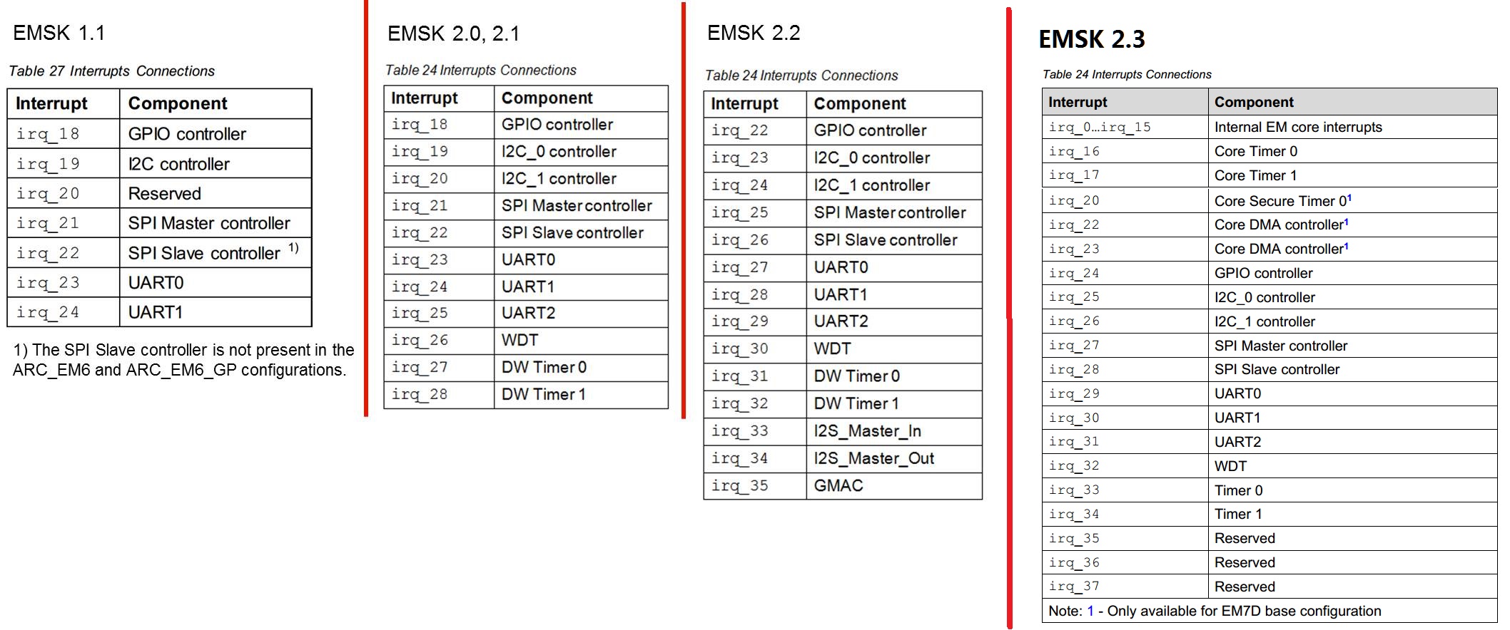
Peripherals interrupts
Peripherals can generate interrupts to the CPU. The interrupt irq assignments are as follows.
Programming and Debugging
Required Hardware and Software
To use embARC OSP applications on the IoTDK board, the following items are required
USB Cable
The USB cable provides power to the board (maximum 500 mA). However, if the board is to run standalone, the universal switching power adaptor (110-240V AC to 5V DC), can be used to power the board
(optional) A collection of PMOD modules.
Set up the EMSK
The EMSK has a bank of DIP switches labeled SW1 that are used to select a configuration. For example, to select ARC EM11D for EMSK 2.3, set bit 2 to the ON position (down), and the others to OFF (up) as shown.
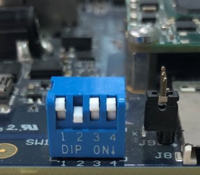
DIP switch settings for ARC EM11D on EMSK 2.3
For exact DIP switch settings for various ARC EM Starter Kit versions, refer to EM Starter Kit section in provided embARC documentation. For complete ARC EM Starter Kit information, see the EM Starter Kit User’s Guide provided with the ARC EM Starter Kit.
Connect the USB cable to connector J7 on the EMSK to USB port on your development host. If using the Ashling Opella-XD for ARC Debug Probe, connect it to the J15 connector on EMSK.
Note
Despite the fact that EMSK 2.3 can be powered by connector J7, it is recommended to always use an AC adapter to supply power of the board.
You can use any terminal emulation program to view UART output from the EMSK. The USB connection provides both the debug channel and RS232 transport. Use PuTTY application on Windows as an example.
Determine which COM port the EMSK is using.
Open the Windows Control Panel and select Device Manager in a Windows environment.
Expand Ports (COM and LPT) in the list. Select USB Serial Port (COM x) and note the COM port number for the ARC board.
Configure serial terminal connection.
Launch PuTTY. Select Serial under Connection type and enter the appropriate COM port string under Serial line.
Choose 115200 baud, 8 bits, 1 stop bit, no parity (115200-8-N-1) in settings.
You can optionally save your settings so they can be easily retrieved every time PuTTY is launched.
Click Open to open the console.
Test serial output with EMSK.
Press the middle (“R”eset) button above the ARC label on the EMSK board to reset the board and run the self-test.
Use EMSK 2.3 as an example. Confirm that you can see the header and self-test message printed to the console.
***********************************
**       Synopsys, Inc.          **
**     ARC EM Starter kit        **
**                               **
** Comprehensive software stacks **
**   available from embARC.org   **
**                               **
***********************************
Firmware   Feb 22 2017, v2.3
Bootloader Feb 22 2017, v1.1
ARC EM11D, core configuration #3

ARC IDENTITY = 0x43
RF_BUILD = 0xc902
TIMER_BUILD = 0x10304
ICCM_BUILD = 0x804
DCCM_BUILD = 0x10804
I_CACHE_BUILD = 0x135104
D_CACHE_BUILD = 0x215104

SelfTest PASSED

Info: No boot image found
(Optional) Connect the PmodWiFi, PmodRF2, and PmodTMP2 modules to the EMSK as shown.
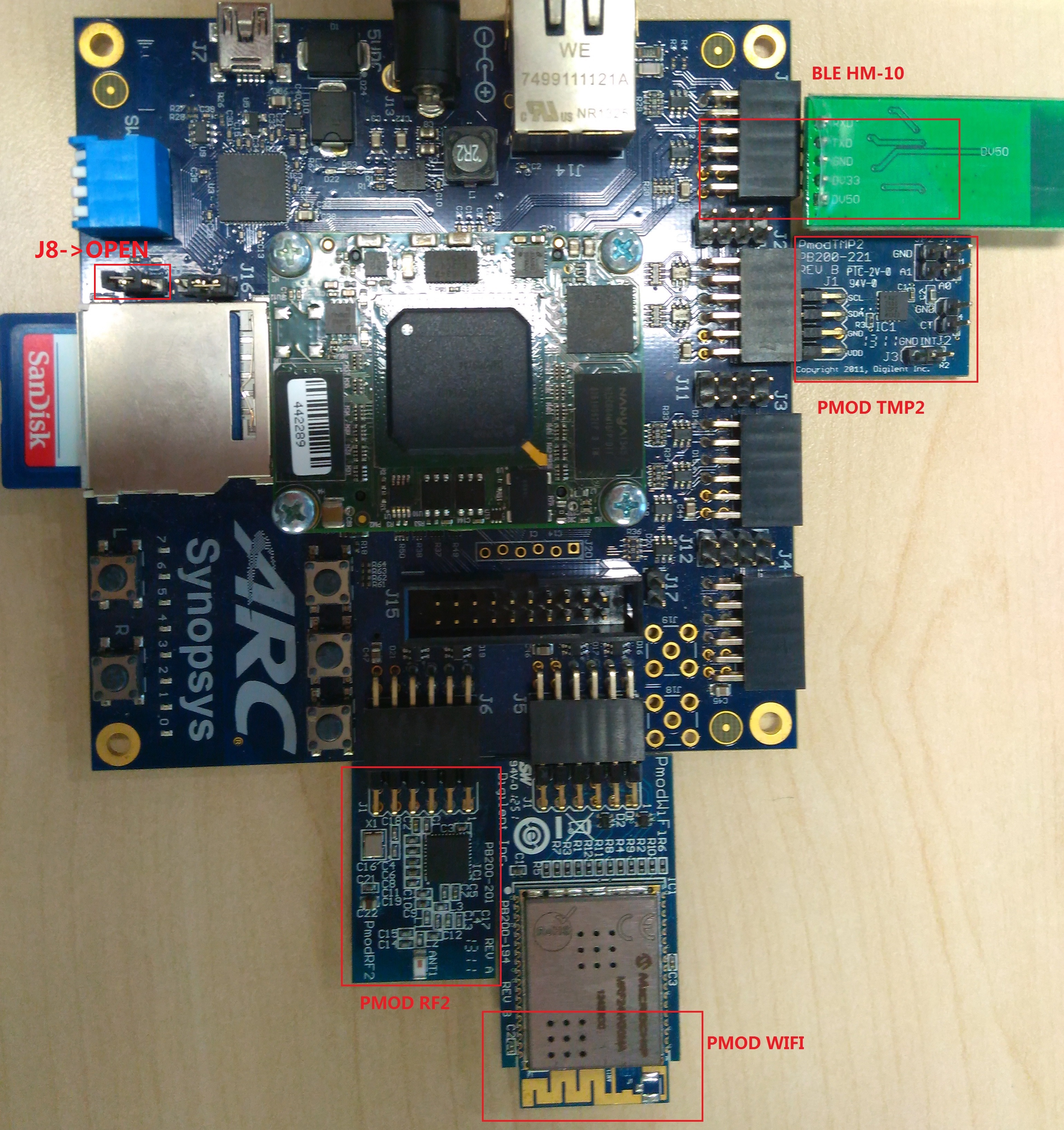
EMSK board connection
Building
Take example_blinky as an example and use the em7d configuration of EMSK 2.2
cd embarc_osp\example\baremetal\blinky
# for ARC GNU toolchain
make TOOLCHAIN=gnu BOARD=emsk BD_VER=22 CUR_CORE=arcem7d
# for MWDT toolchain
make TOOLCHAIN=mw  BOARD=emsk BD_VER=22 CUR_CORE=arcem7d
Running
cd embarc_osp\example\baremetal\blinky
# for ARC GNU toolchain
make TOOLCHAIN=gnu  BOARD=emsk BD_VER=22 CUR_CORE=arcem7d run
# for MWDT toolchain
make TOOLCHAIN=mw  BOARD=emsk BD_VER=22 CUR_CORE=arcem7d run
Debugging
cd embarc_osp\example\baremetal\blinky
# for ARC GNU toolchain
make TOOLCHAIN=gnu  BOARD=emsk BD_VER=22 CUR_CORE=arcem7d gui
# for MWDT toolchain
make TOOLCHAIN=mw  BOARD=emsk BD_VER=22 CUR_CORE=arcem7d gui
Flashing
EMSK has an on board SPI flash, but you cannot directly flash your application into EMSK through debugger. You need other tools/applications (e.g., embarc bootloader) to do this. Please refer example_bootloader