ARC features: AUX registers and timers
Purpose
- To know the auxiliary registers and processor timers of DesignWare® ARC® processors
- To learn how to program auxiliary registers to control the processor timers
Requirements
The following hardware and tools are required:
- PC host
- GNU Toolchain for ARC Processors / MetaWare Development Toolkit
- ARC board (EM Starter Kit / IoT Development Kit)
embarc_osp/arc_labs/labs/lab_timer
Content
- Through reading the corresponding Build Configuration Register (BCR) auxiliary registers of processor timers to get the configuration information
- Through programming the auxiliary registers to initialize, start and stop the timer (here TIMER0 is used)
- By reading the count value of processor timers, get the execution time of a code block
Principles
Auxiliary Registers
The auxiliary register set contains status and control registers, which by default are 32 bits wide to implement the processor control, for example, interrupt and exception management and processor timers. These auxiliary registers occupy a separate 32-bit address space from the normal memory-access (that is load and store) instructions. Auxiliary registers accessed using distinct Load Register (LR), Store Register (SR), and Auxiliary EXchange (AEX) instructions.
The auxiliary register address region 0x60 up to 0x7F and region 0xC0 up to 0xFF is reserved for the Build Configuration Registers (BCRs) that can be used by embedded software or host debug software to detect the configuration of the ARCv2-based hardware. The Build Configuration Registers contain the version of each ARCv2-based extension and also the build-specific configuration information.
In embARC OSP, arc_builtin.h provides API (_arc_aux_read and _arc_aux_read) to access the auxiliary registers.
Processor Timers
The processor timers are two independent 32-bit timers and a 64-bit real-time counter (RTC). Timer0 and Timer1 are identical in operation. The only difference is that these timers are connected to different interrupts. The timers cannot be included in a configuration without interrupts. Each timer is optional and when present, it is connected to a fixed interrupt; interrupt 16 for timer 0 and interrupt 17 for timer 1.
The processor timers are connected to a system clock signal that operates even when the ARCv2-based processor is in the sleep state. The timers can be used to generate interrupt signals that wake the processor from the SLEEP state. The processor timers automatically reset and restart their operation after reaching the limit value. The processor timers can be programmed to count only the clock cycles when the processor is not halted. The processor timers can also be programmed to generate an interrupt or to generate a system Reset upon reaching the limit value. The 64-bit RTC does not generate any interrupts. This timer is used to count the clock cycles atomically.
Through the BCR register 0x75, you can get the configuration information of processor timers
In embARC OSP, arc_timer.h provides API to operate the processor timers.
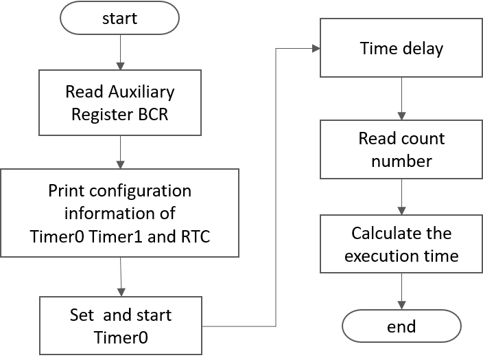
Program flow chart
The code’s flow is shown below:

The code can be divided into 3 parts:
- Part1 : read the BCR of internal timers to check the features
- Part2 : promgram Timer0 by auxiliary registers with the embARC OSP provided API
- Part3 : read the counts to Timer 0 to measure a code block’s execution time
Steps
- Build and Run
$ cd <embarc_root>/arc_labs/labs/lab_timer
# for emsk
$ make BOARD=emsk BD_VER=22 CUR_CORE=arcem7d TOOLCHAIN=gnu run
# for iotdk
$ make BOARD=iotdk TOOLCHAIN=gnu run
- Output
-----------------------------------------------------------
      ____                                _ ____
     |  _ \ _____      _____ _ __ ___  __| | __ ) _   _
     | |_) / _ \ \ /\ / / _ \ '__/ _ \/ _` |  _ \| | | |
     |  __/ (_) \ V  V /  __/ | |  __/ (_| | |_) | |_| |
     |_|   \___/ \_/\_/ \___|_|  \___|\__,_|____/ \__, |
                                                  |___/
                          _       _    ____   ____
            ___ _ __ ___ | |__   / \  |  _ \ / ___|
           / _ \ '_ ` _ \| '_ \ / _ \ | |_) | |
          |  __/ | | | | | |_) / ___ \|  _ <| |___
           \___|_| |_| |_|_.__/_/   \_\_| \_\\____|
     ------------------------------------------------------------

     embARC Build Time: Aug 22 2018, 15:32:54
     Compiler Version: MetaWare, 4.2.1 Compatible Clang 4.0.1 (branches/release_40)
     Does this timer0 exist?  YES
     timer0's operating mode:0x00000003
     timer0's limit value :0x00023280
     timer0's current cnt_number:0x0000c236

     Does this timer1 exist?  YES
     timer1's operating mode:0x00000000
     timer1's limit value :0x00000000
     timer1's current cnt_number:0x00000000

     Does this RTC_timer exist?   NO

     The start_cnt number is:2
     /******** TEST MODE START ********/

     This is TEST CODE.

     This is TEST CODE.

     This is TEST CODE.

     /******** TEST MODE END ********/
     The end_cnt number is:16785931
     The board cpu clock is:144000000

     Total time of TEST CODE BLOCK operation:116
Exercises
- Try to program TIMER1
- Try to create a clock with a tick of 1 second